
To get the best experience for our site, we recommend you upgrade to the latest version of Internet Explorer, or select another web browser, a list of the most popular web browsers can be found below
You can download the main browser here:

Google Chrome

Firefox

IE11
 Position:
Home >
Products
> Fiber Optic Passive Components
> Fiber Optic Switches (FOS)
Position:
Home >
Products
> Fiber Optic Passive Components
> Fiber Optic Switches (FOS)
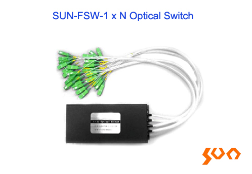
More than 128 channels; Low Loss, High Reliability; Parallel interface (TTL); Modularizing Design

| Type | SUN-FWS-1xN | ||||
| Insertion Loss (dB) | 1 |
45 |
88 |
||
| Typ:1.2 Max.:1.5 | Typ:1.2 Max.:1.5 | Typ.:1.2 Max.:1.5 | |||
| Wavelength Range (nm) | 850 ± 40 / 1300 ± 40 | 1260 ~ 1650 | |||
| Operation Wavelength (nm) | 850/1300 | 1310/1550 | |||
| Return Loss (dB) | SM≥50; MM≥30 | ||||
| Cross-Talk (dB) | ≤-55 | ||||
| PDL (dB) | ≤0.05 | ||||
| WDL (dB) | ≤0.25 | ||||
| TDL (dB) | ≤0.25 | ||||
| Repeatability (dB) | ≤±0.05 | ||||
| Switching Time (ms) | ≤10 (sequence switch time of adjacent channel) | ||||
| Operating life | >107 time | ||||
| Transmission Power (mW) | ≤500 | ||||
| Operation Temp. (°C) | -20 ~ +70 | ||||
| Storage Temp. (°C) | -40 ~ +85 | ||||
| Relative Humidity | 5% ~ 95% | ||||
| Dimensions (mm) | 135 x 40 x 32 (N≤4) | 135 x 64 x 32 (N≤12) | |||
| 184 x 78 x 36 (N≤16) | 184 x 78 x 66 (N≤45) | ||||
| 184 x 156 x 66 (N≤88) | 184 x 220 x 66 (N≤128) | ||||
| 140 x 77.5 x 32 (N≤16) | 140 x 77.5 x 64 (N≤32) | ||||
| Pin No. | Signal Name | I/O | Description |
| 1 | D0 | Input | TTL, Output Channel selection bit 0 |
| 2 | D1 | Input | TTL, Output Channel selection bit 1 |
| 3 | D2 | Input | TTL, Output Channel selection bit 2 |
| 4 | D3 | Input | TTL, Output Channel selection bit 3 |
| 5 | /RESET | Input | TTL, Low Level reset to channel 0. High level Means channel selection bits are effective |
| 6 | /READY | Output | TTL, Ready (High=not ready, Low=ready) |
| 7 | ERROR | Output | TTL, Error (High=Error, Low=No Error) |
| 8 | GND | Input | Ground |
| 9 | +5VDC | Input | 5.0±5% VDC Power Supply (max 550mA) |
| Pin No. | Signal Name | I/O | Description |
| 2 | D0 | Input | TTL, Output Channel selection bit 0 |
| 3 | D1 | Input | TTL, Output Channel selection bit 1 |
| 4 | D2 | Input | TTL, Output Channel selection bit 2 |
| 5 | D3 | Input | TTL, Output Channel selection bit 3 |
| 6 | D4 | Input | TTL, Output Channel selection bit 4 |
| 11 | /RESET | Output | TTL, Low Level reset to channel 0. High level Means channel selection bits are effective |
| 7 | /READY | Output | TTL, Ready (High=not ready, Low=ready) |
| 8 | ERROR | Input | TTL, Error (High=Error, Low=No Error) |
| 1,9 | GND | Input | Ground |
| 15 | +5VDC | Input | 5.0±5% VDC Power Supply (max 50mA) |
| 12 | VM | Input | 5.0±5% VDC Power Supply (max 500mA) |
| 10,13,14 | NA |
| Pin No. | Signal Name | I/O | Description |
| 15 | D0 | Input | TTL, Output Channel selection bit 0 |
| 16 | D1 | Input | TTL, Output Channel selection bit 1 |
| 17 | D2 | Input | TTL, Output Channel selection bit 2 |
| 18 | D3 | Input | TTL, Output Channel selection bit 3 |
| 19 | D4 | Input | TTL, Output Channel selection bit 4 |
| 20 | D5 | Input | TTL, Output Channel selection bit 5 |
| 21 | D6 | Input | TTL, Output Channel selection bit 6 |
| 22 | /RESET | Input | TTL, Low Level reset to channel 0. High level Means channel selection bits are effective |
| 2 | /READY | Output | TTL, Ready (High=not ready, Low=ready) |
| 3 | ERROR | Output | TTL, Error (High=Error, Low=No Error) |
| 1,10,14,23 | GND | Input | Ground |
| 12,25 | +5VDC | Input | 5.0±5% VDC Power Supply (max 50mA) |
| 13 | VM | Input | 5.0±5% or 12.0±5% VDC Power Supply , N<45 Max Current Supply 500mA N<88 Max Current Supply 750mA N<128 Max Current Supply 1000mA |
| 11,24 | |||
| 4,5,6,7,8,9 | NA |


| N | A | B | C | D | E | F |
| Channel | Mode | Wavelength (nm) |
Fiber type | Fiber diameter | Fiber Length | Connector |
| N = 1, 2, 3… | S:SM M:MM |
85: 850 13: 1310 15: 1550 1315:1310/1550 X: Other |
5:50/125 6:62.5/125 9: 9/125 X: Other |
900:900um; 2:2.0mm 3: 3.0mm X: Other |
L1:1.0m X: Other |
None FC: FC/PC AFC: FC/APC SC: SC/PC ASC: SC/APC ST: ST/PC AST: ST/APC LC: LC/PC ALC: LC/APC X: Other |
| H | ||||||
| Dimension | ||||||
| 01:135x40x32-DB9-F 02:135x64x32-DB9 03:184x78x36-DB15-F 04:184x78x66-DB25 05:184x156x66-DB25 06:184x220x66-DB25 07:140x77.5x32-DB15-C 08:140x77.5x64-DB15-C X:Others |
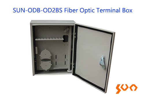
SUN-ODB-OD2BS Terminal Box
Model: SUN-ODB-OD2BS
Outdoor wall mount, Max cores: 36 ⁄ 72, IP65, 1:32 1:64 Splitter
Features
 Material: cold-rolled steel Protection Rating IP65 Outdoor wall mount FC square/SC/ST adapter panel Suitable for 1:32 or 1:64 PLC splitter
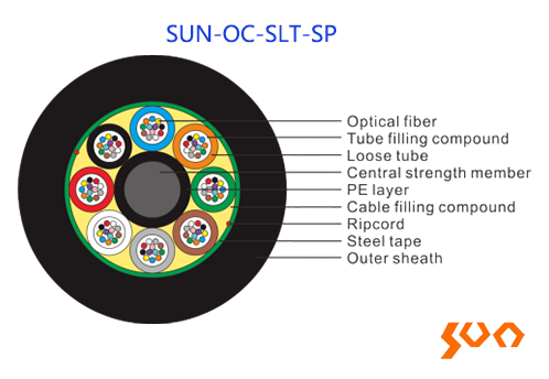
SUN-OC-SLT-SP Stranded Loose Tube Light-armored (Steel Tape) Cable (GYTS)
Model: SUN-OC-SLT-SP
GYTS, Loose Tube Light-armored (Steel Tape) Cable, 2-144cores
Features
Good mechanical and temperature performance High hydrolysis resistance and high strength loose tube Good crush resistance and flexibility High tensile strength ensured by steel wire Good moisture-proof ensured by PSP Gopher protected cable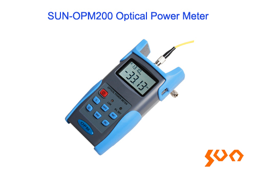
SUN-OPM200 Optical Power Meter
Model: SUN-OPM200
FC ⁄ SC ⁄ ST, REF, backlight control, USB port
Features
User self-calibration function Power measurements in dBm or mW Auto power off after 10 minutes without operation Standard FC/SC/ST interchangeable port Backlight LCD display for night operation REF setting function Intelligent backlight control Auto wavelength and frequency identification High storage capacity USB communication port for data transfer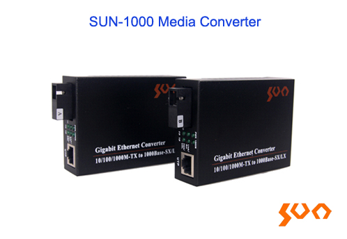
SUN-1000 Ethernet Media Converter
Model: SUN-1000
10 ⁄ 100 ⁄ 1000Mbps, 1xRJ45, 1xOptical port
Features
Compliance with IEEE standards MTBF of more than 50000 hours Full & half duplex operation and auto-negotiation Electric interface self-adapting parallel/crossover connections Longest 1552 byte data packet transmission QoS ensuring VoIP data packet transmission STP Spanning Tree forming a redundant network Low power consumption and low heat for longtime stable operation Single/Multi mode and Single/Dual fiber transmission modes Network Management Function (optional)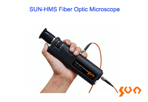
SUN-HMS Fiber Optic Microscope
Model: SUN-HMS
200X 400X Optical Magnification, FC ⁄ SC ⁄ ST, LC ⁄ MU, SMA905 interfaces
Features
UPC or APC end face inspection Built-in infrared attenuation filter for safety and reliability On/off switch control Precise focal length adjustment Suitable for various of fiber optic connector end faces inspection


 ics@suntelecom.cn
  +86 18964888554
 Building No.145, Lane 666 Xianing Road, Jinshan Industrial Zone, Shanghai 201506, China
Copyright ©1989-2026 ALL Rights Reserved
ICP (Shanghai) Number: 13005159


 +86 21 60138638